Class 16 (Analog Filter Design)
Video Lectures
Single Pole filters
By placing poles and zeros in the complex plane, we can design filters. Typically, we use pole-zero placement to design prototype low-pass filters. We then use the prototype lowpass filters to design highpass or bandpass filters. Therefore, we will look at specifically at how to design a low pass filters in this lecture.
Single pole low-pass filters
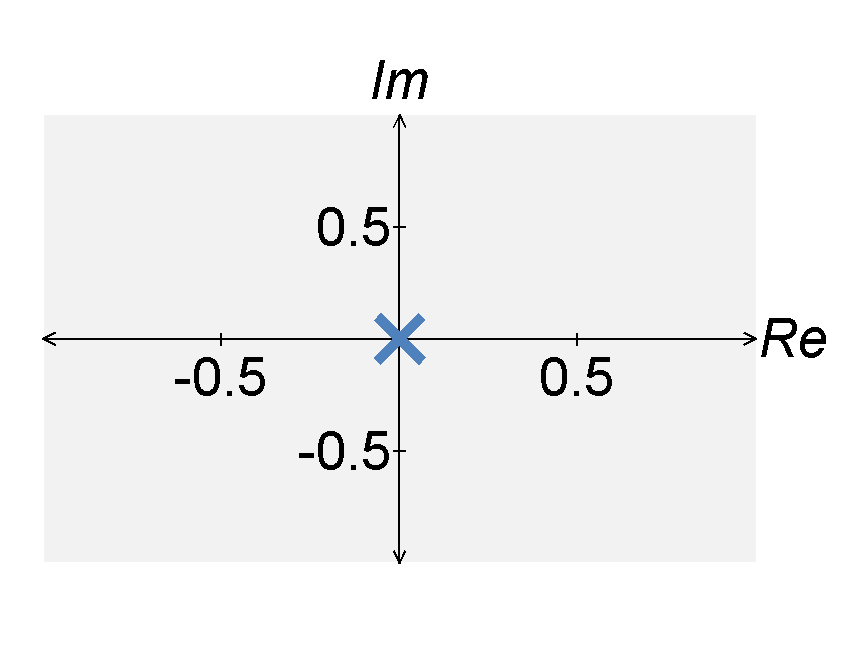
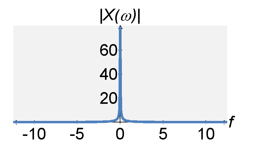
To understand how pole placement can be used to design filter, consider the Laplace representation (transfer function) of a system defined by $$H(s) = \frac{1}{s} \; .$$ The system has one pole at $s = 0$. If we let $s = j \omega$, we find that the magnitude response of the system is infinity at $\omega = 0$, i.e., $|H(0)| = \infty$. In a sense, this is a low pass filter. Yet, it has an infinite gain at $\omega = 0$, which not desirable.
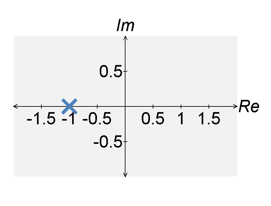
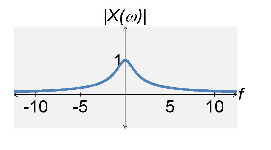
To reduce the gain, we can move the pole left in the complex plane. If we move the pole to $s = -1$, the transfer function becomes $$H(s) = \frac{q}{s+1} \; .$$ If $s = j \omega$, the magnitude response of $H(s)$ can be expressed by $$|H(s)| = \frac{q}{|j\omega + 1|} = \frac{1}{\sqrt{1 + \omega^2}} \; .$$ From this expression, we see that the maximum absolute value of the transfer function still occurs at $\omega = 0$. However, the maximum value is now $|H(0)| = 1$ rather than infinity.
Adjustable cut-off frequency
We define the cut-off frequency $\omega_c$ as the angular frequency $\omega$ such that $$|H(\omega_c)|^2 = \frac{1}{2} \quad , \quad |H(\omega_c)| = \frac{1}{\sqrt{2}} \; .$$ The cut-off frequency of the above low-pass filter is $\omega = 1$.
In general, we want our filters to have an adjustable cut-off frequency. We change the cut-off frequency $\omega_c$ of a filter by stetching in frequency. We transform $\omega$ into $\omega / \omega_c$. If we apply this to our single pole filter, we get $$H(s) = \frac{1}{ 1 + \frac{s}{\omega_c}} = \frac{\omega_c}{ s+ \omega_c} \; . $$ The cut-off frequency for this filter is $$\begin{eqnarray*} |H(\omega)|^2 = \frac{\omega_c^2}{\omega^2 + \omega_c^2} &=& \frac{1}{2} \\ \omega_c^2 &=& (1/2)(\omega^2 + \omega_c^2) \\ \omega &=& \omega_c \; . \end{eqnarray*}$$ Therefore we have a low-pass filter with a gain of $1$ at $\omega = 0$ and an adjustable cut-off frequency of $\omega = \omega_c$.
Multi-pole filters
In the previous section, we designed a low-pass filter with a desired gain and a desired cut-off frequency. However, the cut-off is not very sharp and the pass-band is not very constant. To improve these characteristics, we can add additional poles. As a guide, we consider few model filters that are commonly used for filter design. We present each filter for a cutoff frequency of $\omega_c = 1$. We can later change the cut-off frequency by frequency stretching.
Butterworth filter
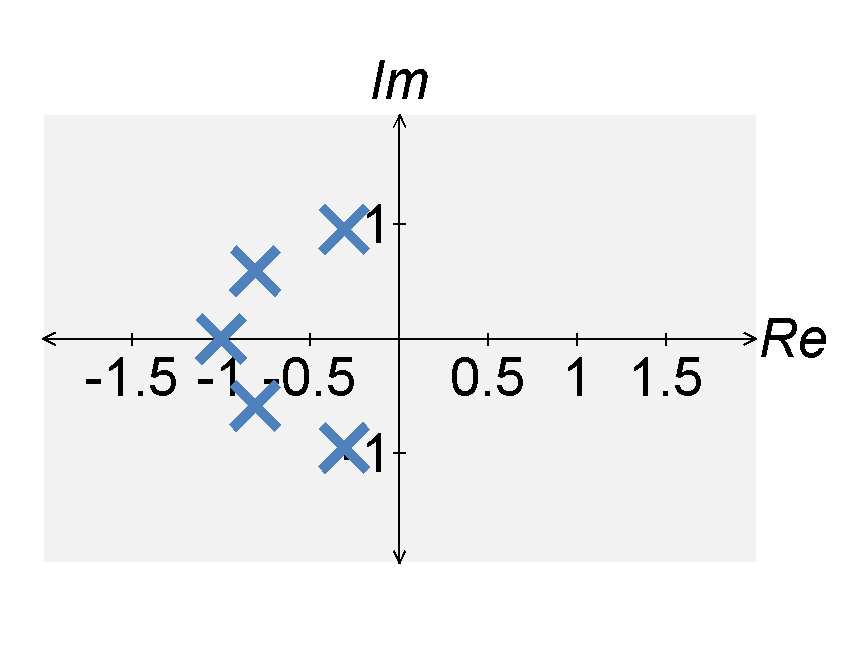
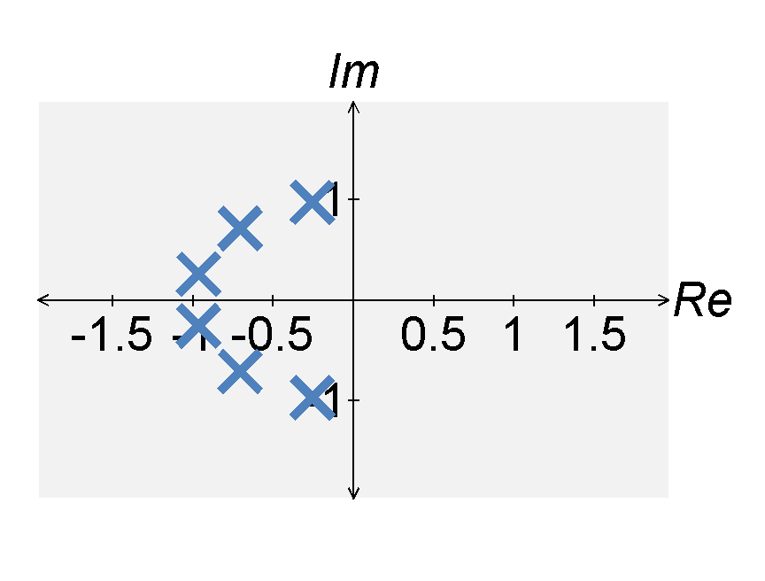
The Butterworth filter with a cutoff frequency of $\omega = 1$ is defined by the magnitude of the transfer function $$|H(j \omega)| = \frac{1}{ \sqrt{1 + \omega^{2n}}}$$ The squared-magnitude of this transfer function is defined by $$\left. |H(j \omega)|^2 \right|_{s = j \omega} = H(s)H(-s) = \frac{1}{ 1 + s^{2n}} = \frac{1}{\prod_{k}^{n} (s - s_k)}$$ The $k$th pole of $|H(j \omega)|^2$, i.e., $s_k$, is defined by $$s_k = (-1)^{\frac{1}{2n}} = e^{\frac{j(2 k - 1) \pi}{2n}} \quad , \quad \textrm{for } 1 \leq k \leq 2 n \; .$$ These poles lie in a circle around the complex plane.
We defined $H(s)$ by taking only the poles on the left-hand side (hence, we want the Fourier transform to exist and the system to be stable). If we do this, we find that the poles of the $n$th order Butterworth filter are $$s_k = e^{\frac{j(2 k + n - 1) \pi}{2n}} \quad , \quad \textrm{for } 1 \leq k \leq n \; .$$ The Butterworth filter is defined by several characteristics, including:
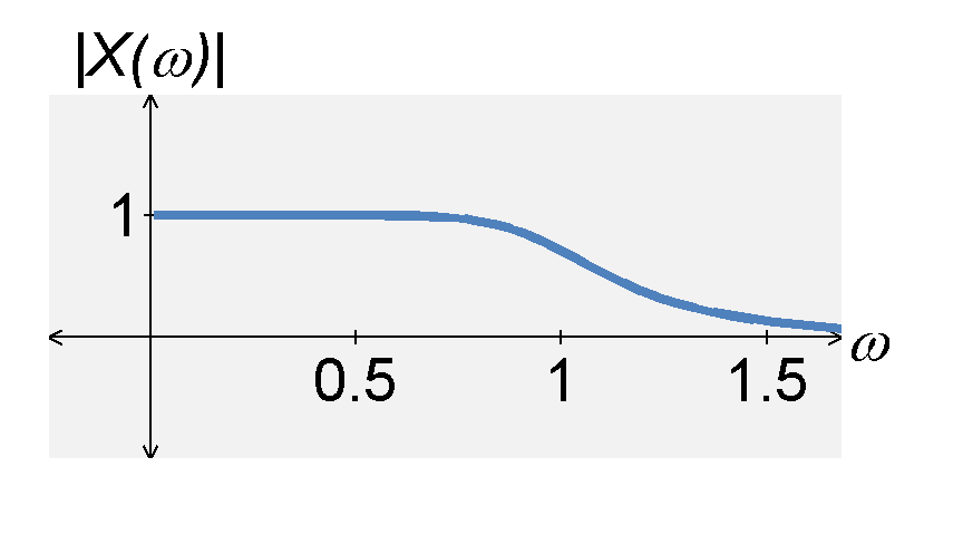
- it is maximally flat at $\omega = 0$.
- it has a cutoff frequency $|H(\omega)|=1/\sqrt{2}$ at $\omega = \omega_c$.
- for large $n$, the magnitude response approaches an ideal filter.
Chebyshev filter
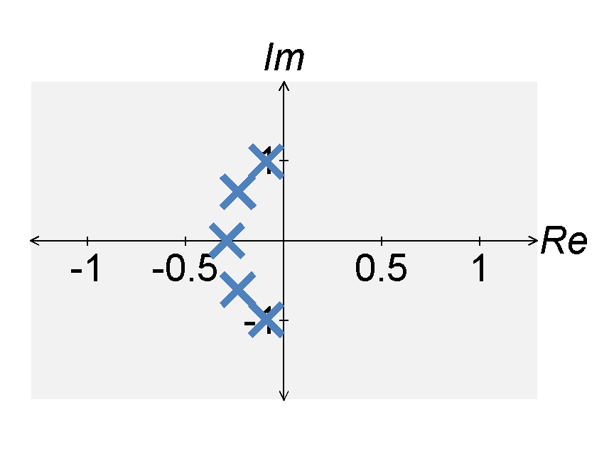
The $n$th-order Chebyshev filter is defined by the magnitude of the transfer function $$|H(j \omega)| = \frac{1}{ \sqrt{1 + \epsilon^2 C_n^2(\omega)}} \; .$$ The function $C_n(\omega)$ is known as the $n$th-order Chebyshev polynomial, defined by $$C_n(\omega) = \cos(n \cos^{-1}(\omega) ) \; .$$ The poles of the $n$th order Chebyshev filter are $$s_k = - \sin\left[ \frac{(2 k - 1)\pi}{2 n} \right] \sinh\left[ \frac{1}{n} \sinh^{-1}\left( \frac{1}{\epsilon} \right) \right] + j \cos\left[ \frac{(2 k - 1)\pi}{2 n} \right] \cosh\left[ \frac{1}{n} \sinh^{-1}\left( \frac{1}{\epsilon} \right) \right] $$ The Chebyshev filter is defined by several characteristics, including:
- it has ripples in the passband and is smooth in the stopband.
- the gain at $\omega = 0$ is $|H(0)| = 1$ if $n$ is odd and $|H(0)| = (1+\epsilon^2)^{-1/2}$ if $n$ is even.
- the ratio between the maximum and minimum ripples in the passband is $(1+\epsilon^2)^{-1/2}$.
- if $\epsilon$ is reduced (i.e., the ripple size is reduced), then the stopband attenuation is reduced.
- it has a sharper cut-off than a Butterworth filter, but at the expense of passband rippling
Elliptic filter
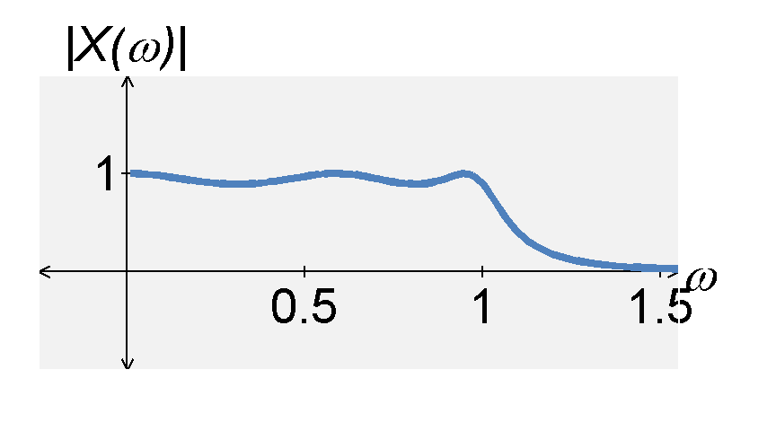
The $n$th-order Elliptic filter is defined by the magnitude of the transfer function transfer function $$|H(j \omega)| = \frac{1}{ \sqrt{1 + \epsilon^2 R_n^2(\omega)}} \; .$$ The function $R_n(\omega)$ is known as the $n$th-order Chebyshev rational function. The Elliptic filter is defined by several characteristics, including:
- it has ripples in the passband and the stopband.
- the ratio is larger than the Chebyshev filter
- it has a quicker transition between the passband and stopband, compared with the Butterworth and Chebyshev filters
- it has poles and zeros, but they are much more difficult to compute compared with the Butterworth and Chebyshev filters
Building a high-pass filter from a lowpass filter
We can transform any low-pass filter into a high-pass filter by replacing $s$ in the prototype low-pass filter (where $\omega_c = 1$) with $\omega_p / s$. The frequency $\omega_p$ is the cut-off frequency for the high-pass filter.
Additional Resources
- From this course
- From Richard Baraniuk's open textbook
- Other online resources