
Project 3B
Invisibility Cloak
Now lets try a COMSOL simulation of the cloak. (We can’t use CST because CST does not allow off diagonal elements of the permittivity and permeability tensors.)
Unfortunately, we do not have COMSOL installed on the machines in 2555 MEB, so we will need to run COMSL remotely on Engman Lab machines. Instructions fo remote access are here.
Once you have the remote window open, click the Start menu, and then type COMSOL. Then click (Classkit License) COMSOL Multiphysics 5.4, to launch the application.
Then select Model Wizard, and then 2D. We will use a 2D solver since the cloak experiment was performed in a 2D waveguide environment.
Select Electromagnetic Waves, Frequency Domain (emw) from the Radio Frequency list, then click Add.

Then click the green arrow to add a Study. Select Frequency Domain from the General Studies category, and then click Done.

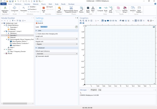
You should now see the three column workspace with: Model Builder, Settings, and Graphics.
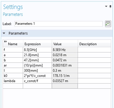
Now let’s create global parameters that we need. ClickParameters 1, and create the following global parameters.
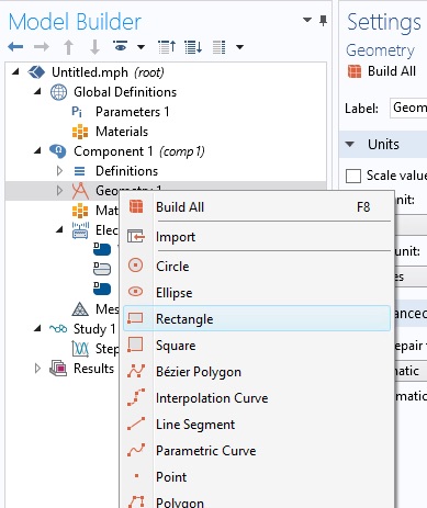
Now let’s create some geometry. First, the overall domain. Create a Rectangle by right clicking the Geometry 1 object.
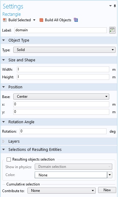
Fill in the Width and Height using your global parameter, l , and change the Position to Center.
Now create the inner and outer circles of the cloak. Right click Geometry 1 and select Circle. Set the radius to the global parameter a.
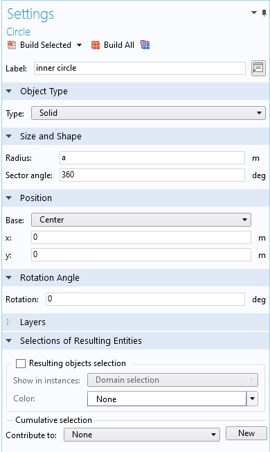
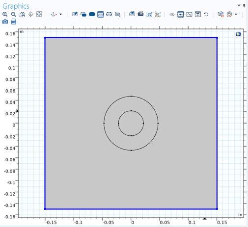
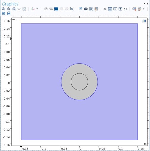
Then make the outer circle with global parameter b. Your graphics window should look like this. You may need to click Build All to render the objects.
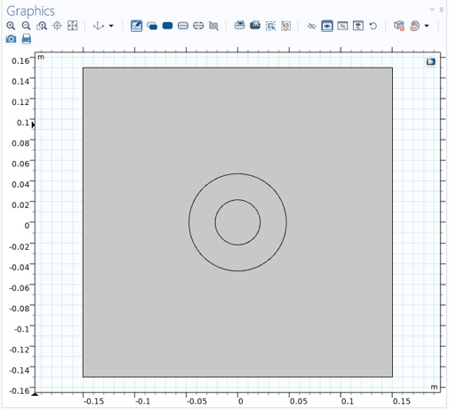
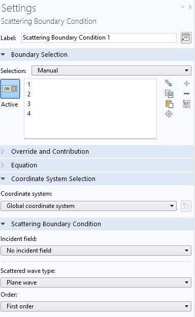
Now let’s set some boundary conditions. From the Physics tab select a Scattering Boundary Condition.
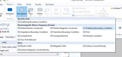
Then in the Graphics window, click the Select Boundaries item.
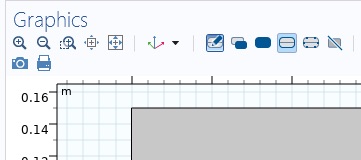
...and select the four outer boundaries (with a single click).
The Settings pane will look like this.
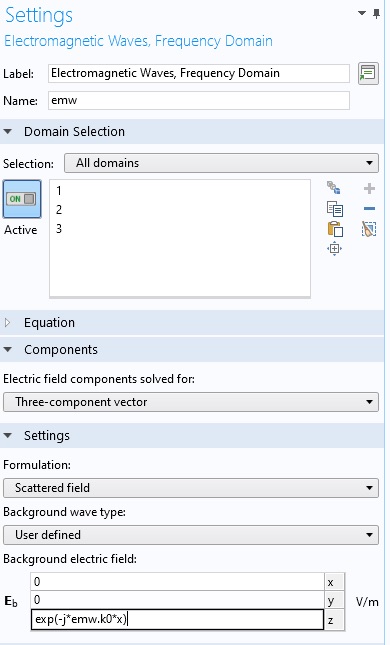
Now let’s create the incident/background field. Click Electromagnetic Waves, Frequency Domain (emw) in the Model Builder pane. In the Formulation menu, select Scattered Field. Then enter a Background electric field.
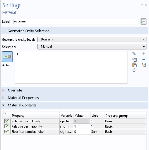
Now let’s create the material properties and assign them to domains. Start with the space around the cloak. Right click Component 1/Materials, in the Model Builder, and select Blank Material. Fill in the background epsilonr and mur, and assign it only to domain 1 (the area around the cloak). You may need to delete some other domains. I renamed it vacuum.
Note the highlighted domain.
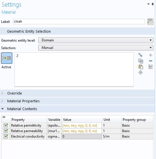
Now create the cloak material and assign it to domain 2. The epslionr and mur will be the anisotropic expression:
{ nxx, nxy, nyy, 0, 0, nz}
we will assign values to these variables later.
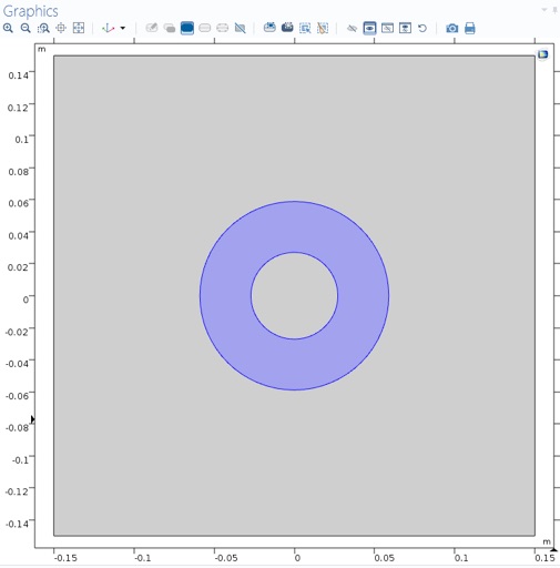
For the object to be cloaked we will use a copper cylinder (as was used in the original experiment). Right Component 1/Materials again, and select Add Material from library...
In the new pane that opens to the right, click Built-In, and then right click Copper, and select Add to Component 1.
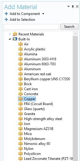
Assign the material to domain 3, the inside of the cloak.
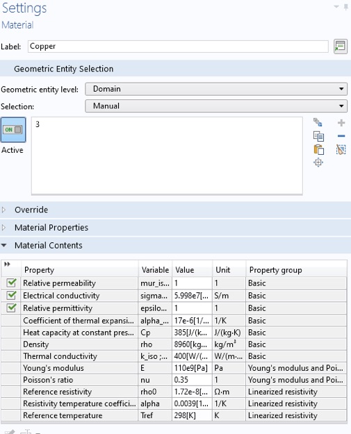
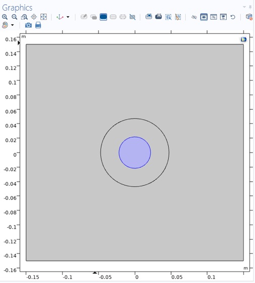
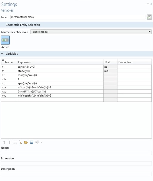
Now we will assign values to the cloak material variables for some different configurations. Right click Component 1/Definitions and select Variables. First create the ideal cloak configuration.
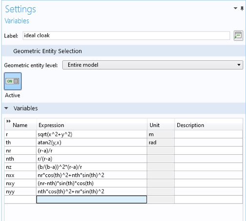
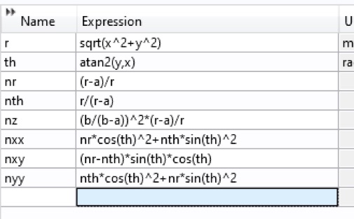
Zooming in, we see the formulas for the ideal cloak properties from the article and the formulas relating cylindrical and cartesian coordinates.
Now choose our desired frequency for the study. Select Frequency Domain under Study 1 in the Model Builder. Enter the global parameter in the Frequencies box.
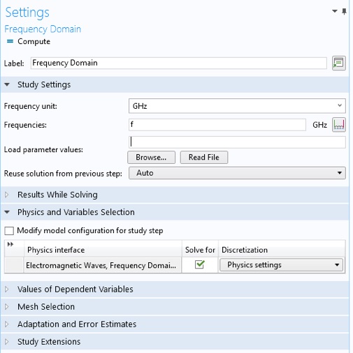
COMSOL does not know how to choose the mesh settings for our anisotropic materials. We will manually select a mesh size.
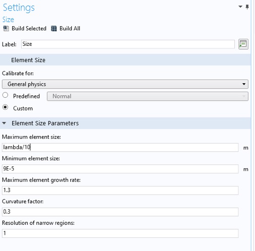
Click Component 1/Mesh 1. In the Settings tab select User-controlled mesh from the Sequence type: menu. Now click
Component 1/Mesh 1/Size. Enter lambda/10 for the Maximum element size:
To simulate, click Compute from: the Study tab, right-click study menu in the Model Builder, or in the Settings pane.
To start we will plot the z-component of the total electric field. Click Results/Electric Field (emw)/Surface. Change the plotted expression to emw.Ez from emw.normE.
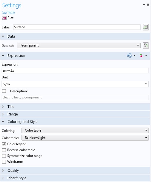
Click Plot.
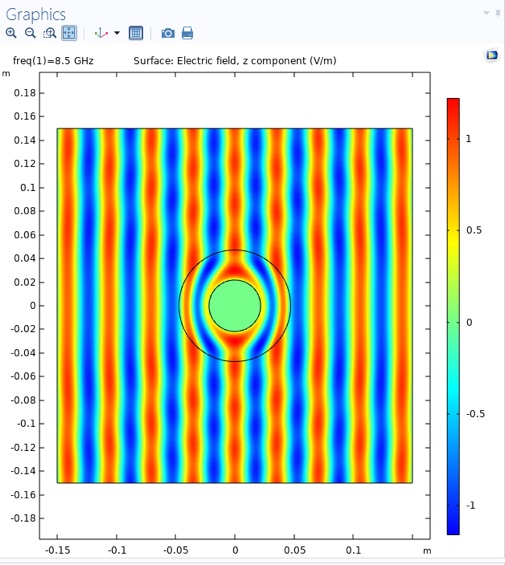
Now we want to predict what a real cloak measurement might look like. There are three ways in which a real cloak measurement differs from the ideal case.
1. The ideal cloak has continuously varying material properties. Our real cloak has eight unit cells radially. To approximate this, we will change the COMSOL material properties to have just eight, discrete, step-wise values for the material properties.
2. The real cloak was designed to match what we called the "reduced" material properties. These properties can create an approximate cloaking behavior. We will use the "reduced" material specification.
3. The ideal cloak matches the theoretical specified material properties from the transformation design method. Our real material properties may only approximately match the ideal specification. The real parts of material properties may deviate slightly and the imaginary parts will be non-zero, i.e. the materials will be lossy. Some electromagnetic energy will be converted to heat.
The material properties sourced from the class are given below.
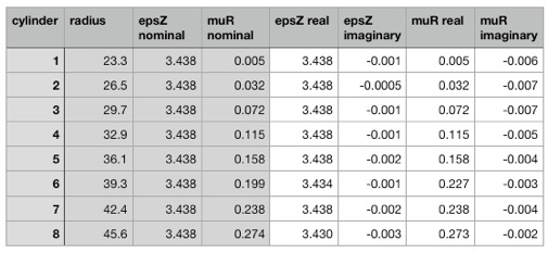
Now create four functions for the real and imaginary parts of epsz and mur. Right click on Global Definitions and select Functions >> Interpolation.
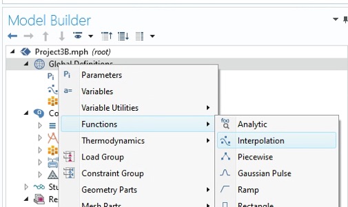
Using our data table create the function for the real part of eps. Be sure to give it an appropriate name, label and units, and set the Interpolation to Nearest Neighbor and the Extrapolation to Constant.
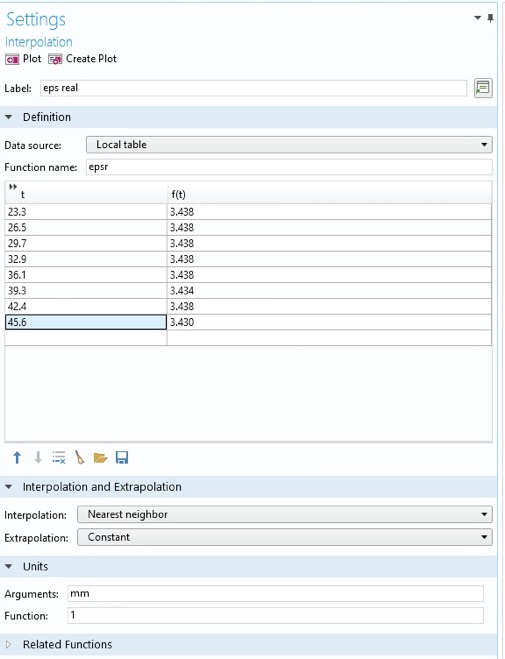
When done, right click the function in the Model Builder pane and duplicate. Fill out this new function to be the imaginary part of eps.
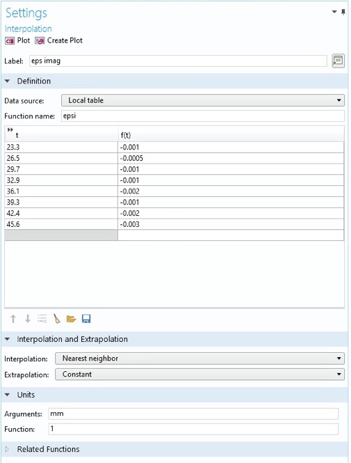
Do the same for the real and imaginary parts of mu. Plot the real part of mu to see if it looks like the plot below. Can you see the value that was a bit off the target?
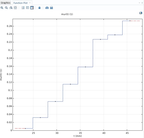
Now duplicate the ideal cloak material properties we created earlier. They should be under Component 1 >> Definitions, in the Model Builder. Set up these material properties for the real metamaterial properties using the functions we just created.
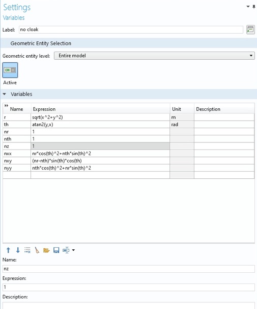
Also set up some material properties fo the "no cloak" case.
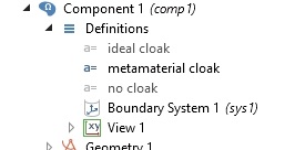
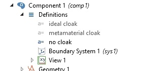
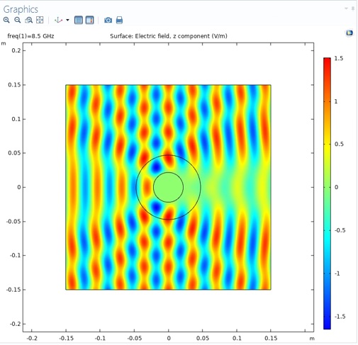
You need to disable all but one of these three definitions to simulate each case. Do this with the right click menu. Here we will see what the metamaterial cloak looks like. Click Compute.
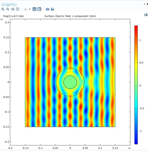
Then try the "no cloak" case.
Include in your report:
4. Include a screen grab of a plot of Ez and normE for each configuration: ideal cloak, metamaterial cloak, and no cloak. Make sure the color scale is included.
5. From the normE plots, estimate the largest positive and negative deviation from 1, along the edges of the simulation domain. Do this for each configuration.
6. To detect the object hidden by the metamaterial cloak, is it best to look: in front, in back, or on the side?